The parameters for this assignment were pretty simple, the container cannot be a cube, and it must be able to stand on at least one side level. We were given a 4” x 4” template with instructions to only cut along the lines and to stop a cut at an intersection point. We could cut pieces off the template, but could not cut parts or chunks out, they had to be straight cuts. We also needed to do male/female junctions so both pieces would fit together securely.
I initially did not know how to approach this assignment. I started with the idea of a cube, then quickly realized, that a cube was the opposite direction to lean into, for this assignment. I decided to approach ensuring I had something available for it to “stand” on, then went to rearrange pieces in a way that I found interesting. Working with the paper template was freeing, realizing if I did not like how things were coming together, I could use tape to secure the pieces and try again. Having the freedom to make mistakes and try as many times as I needed, allowed me the freedom to relax and let the container reveal itself.
Software used: Auto Cad
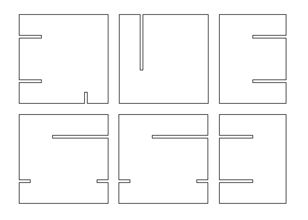
This is an image of the CAD file used to print the templates onto the board used for the final product. We needed to consider how we oriented the objects to allow for greatest material utilization, to reduce waste.
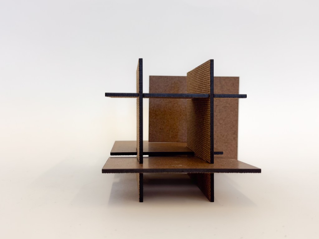
Image 1: Front
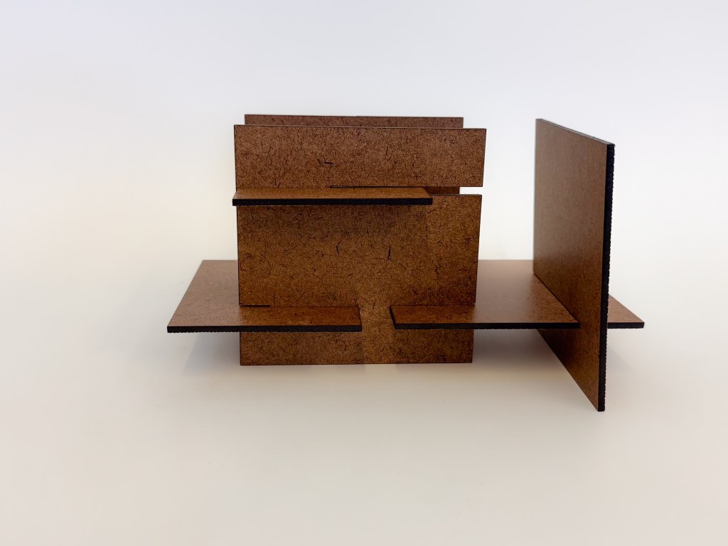
View from facing what could be considered the front of the object. To the right is a large partial-wall that does not span the entire width of the object. Lines seem like they continue through, at first glance, but they are broken, allowing the object to be dynamic.
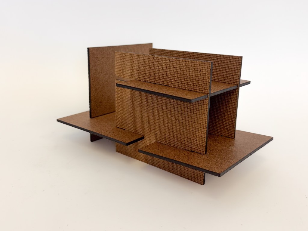
Image 2: Front perspective
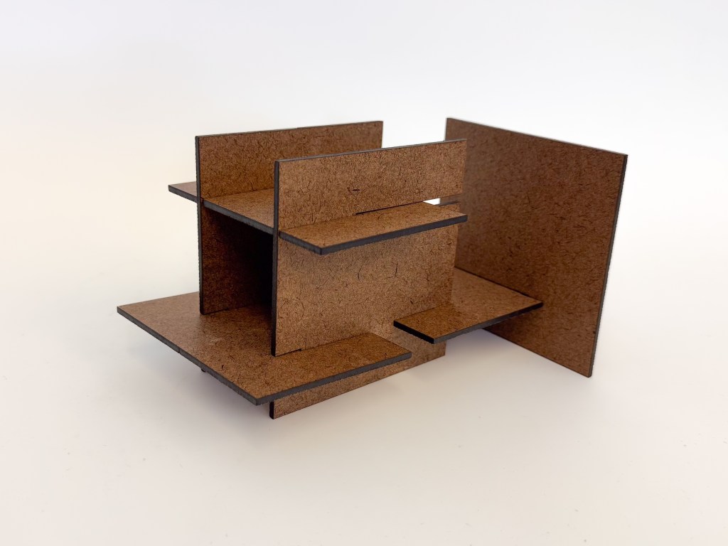
From where you viewed the object for image 1, this view moves to the left and at an angle, so the shape is further revealed.
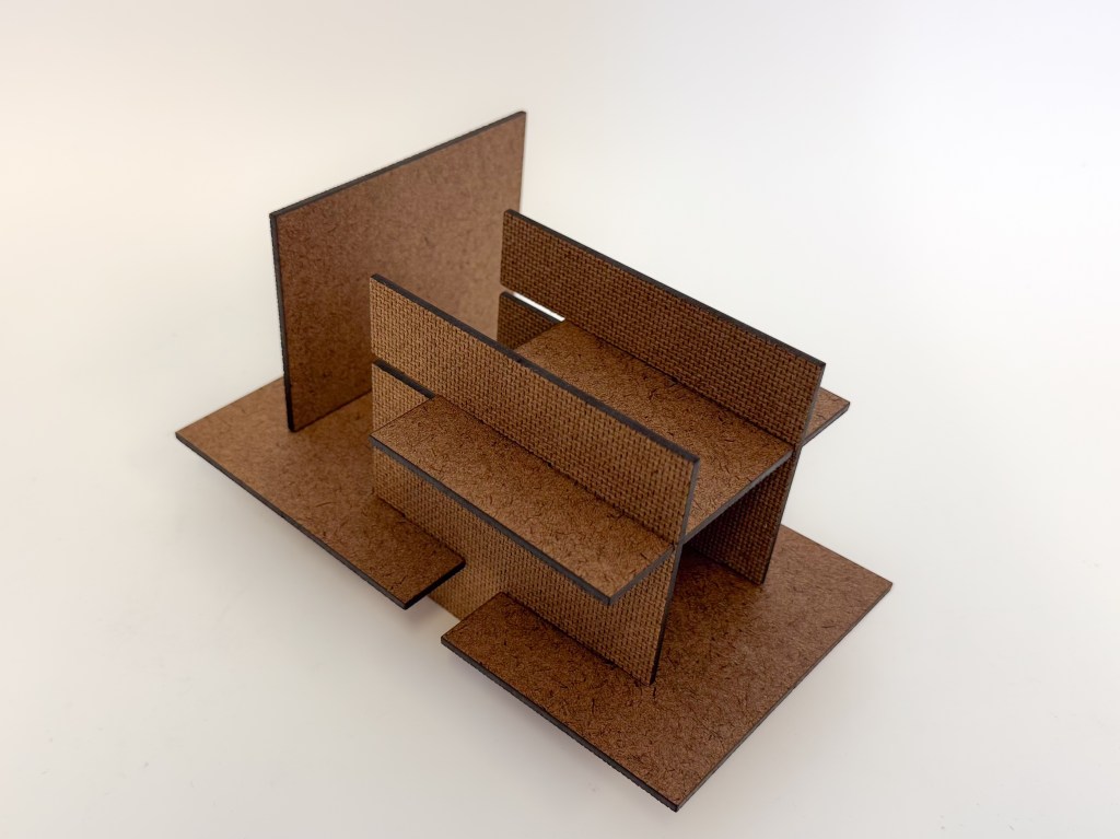
Image 3: Left side through
Continuing your journey around the object to your left, you land at the side. Seeing through the image, with the large partial wall revealing its incompleteness across the width of the structure. This perspective also reveals how the structure does want symmetry and balance, showing a hidden cube.
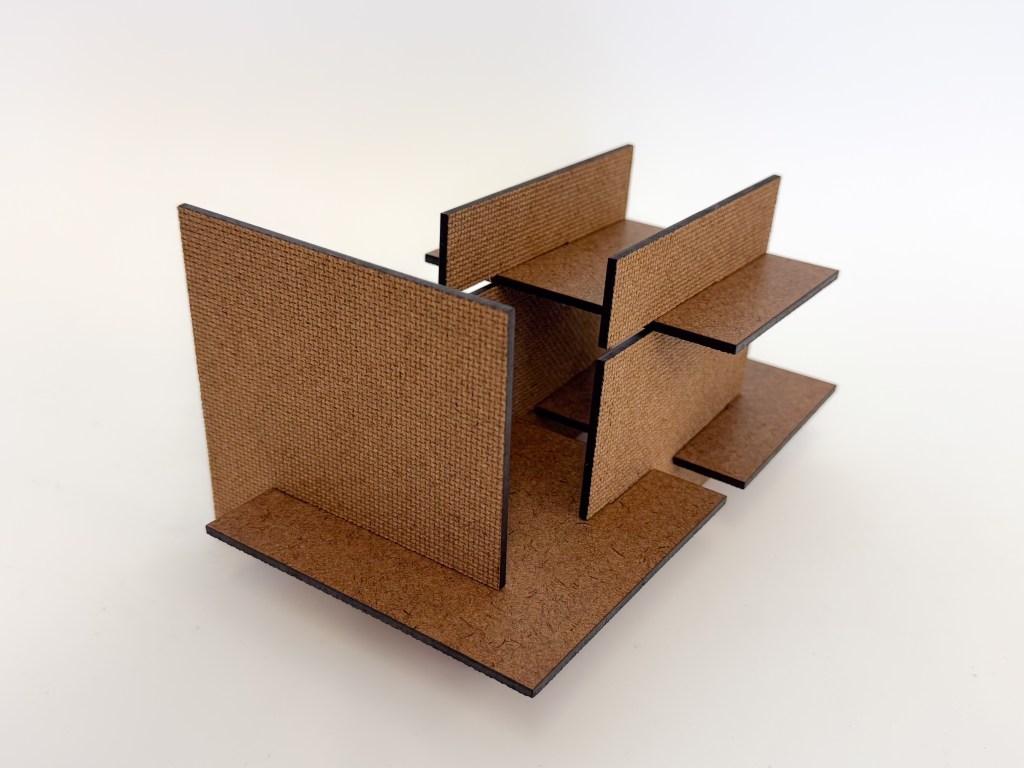
Image 4: Left rear perspective
Now at the left rear perspective, we can see how the front and back of the structure nearly mirror each other with the one difference being how the large partial wall plays with the depth and space.
Image 5: Top left rear perspective
Rising from our previous vantage point to see the image from above, we can see how open the space really is. This space allows negative space to exist comfortably with relaxed sturdiness.
Image 6: Right top rear perspective
Finishing our circle to the right rear perspective we can see how imposing the large partial wall commands the space. This piece halts and creates a stopping point for light and flow. The eye will have to deviate to travel around the wall.
